
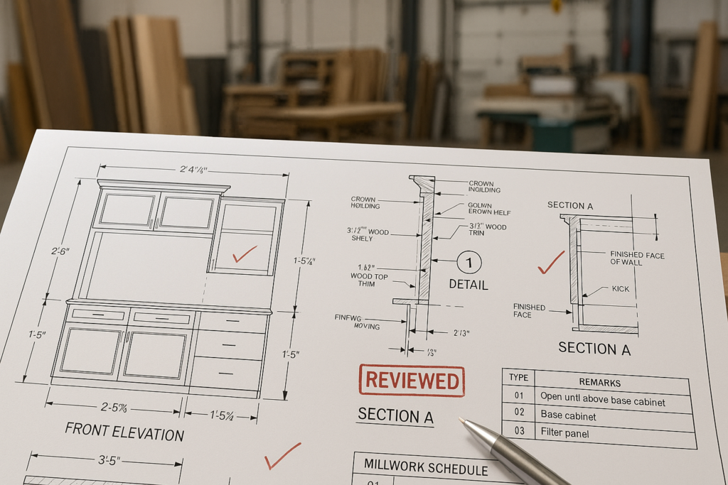
How working drawings for millwork help avoid costly fabrication mistakes
Millwork shop drawings help avoid costly fabrication mistakes by turning design intent into buildable, measurable, approvable instructions. In practical terms, working drawings for millwork typically include dimensions, elevations, sections, material callouts, hardware information, finish notes, attachment details, and coordination notes that fabricators, installers, architects, and general contractors can all review before production starts. When these drawings are complete and coordinated, they reduce rework, RFIs, approval delays, field conflicts, and expensive remakes.
For general contractors, architects, millwork shops, and project managers, the value is straightforward: better drawings lead to fewer assumptions. If a casework run, reception desk, wall panel system, or closet installation is fabricated from incomplete or inconsistent information, the resulting error can affect schedule, finish quality, fit, and owner satisfaction. That is why accurate architectural shop drawings and clean millwork submittals are essential at the pre-fabrication stage.
This guide explains what working drawings for millwork include, how they affect approval and fabrication outcomes, what each project stakeholder should check, and which common mistakes cause avoidable delays. It also shows where MillworkIQ fits in as a practical drafting, redline cleanup, and submittal support partner.
What working drawings for millwork include
At a minimum, working drawings for millwork should communicate enough information for review, fabrication, and installation without relying on guesswork. Exact requirements vary by project scope, specifications, and architect preferences, but most strong millwork shop drawings include the following core elements.
1. Plans, elevations, and sections
These views show the overall layout, front appearance, vertical relationships, and internal build-up of the millwork item or assembly. For example:
- A plan may show the footprint of a reception desk and relation to walls, columns, or floor outlets.
- An elevation may show drawer banks, open shelves, reveals, and finished heights.
- A section may show substrate thickness, countertop build-up, toe kick construction, and fastening method.
2. Accurate dimensions
Dimensions are one of the most important parts of millwork drafting. Drawings should show overall size, component sizes, critical clearances, and installation tolerances where needed. This often includes:
- Overall width, depth, and height
- Opening sizes
- Panel thicknesses
- Countertop overhangs
- Appliance or equipment clearances
- Field verification notes for site-dependent dimensions
If dimensions are missing, conflicting, or not tied back to architectural conditions, fabrication errors become much more likely.
3. Material and construction callouts
Good shop drawings identify what each visible and non-visible component is made from. Depending on project requirements, this can include:
- Core material
- Face veneer or laminate
- Solid wood components
- Edge treatment
- Backing requirements
- Fire-rated or moisture-resistant material notes
Without these callouts, approvals can stall because reviewers cannot confirm compliance with specifications.
4. Hardware and accessory information
Casework and custom architectural millwork often depend on hinges, drawer slides, pulls, locks, grommets, brackets, and specialty supports. Drawings should indicate:
- Hardware type and location
- Swing direction or drawer function
- Special support conditions
- Access panel requirements
- Any owner-furnished or vendor-supplied items that affect fabrication
5. Finish notes and visual intent
Many approval comments arise because finish intent is not clear. Millwork shop drawings should reference finish schedules, sheen, grain direction where relevant, and any requirements for matching adjacent components. For visible feature pieces, enlarged details may be needed to show reveals, seam locations, or edge profiles.
6. Attachment and installation details
Even excellent fabrication details can fail in the field if installation assumptions are wrong. Working drawings should explain how units are secured, supported, aligned, or scribed to surrounding construction. This is especially important for:
- Wall panels
- Floating vanities
- Suspended shelves
- Tall casework
- Large reception desks
- Integrated seating or trim conditions
7. Coordination notes
Architectural shop drawings should also identify dependencies on field conditions, MEP rough-ins, blocking, slab variation, ceiling alignment, and adjacent trades. These notes can prevent approval from moving forward on assumptions that later fail in the field.
How working drawings for millwork affect fabrication and approvals
Working drawings for millwork are not just a formality. They are the bridge between concept and production. If the bridge is weak, the project pays for it later.
They translate design intent into fabrication logic
Architectural drawings often show scope and design direction, but they may not include every fabrication-level detail needed by a shop. The purpose of millwork shop drawings is to fill that gap. They show how the designed object will actually be built.
For example, an architect may show a clean wood feature wall with integrated reveals. The millwork shop drawing must then define panel sizes, substrate, seam placement, fastening approach, reveal dimensions, and alignment with doors, lighting, or adjacent stone.
They support cleaner millwork submittals
Submittals are easier to review when drawings are organized, legible, and coordinated with specs and field conditions. According to common industry practice for submittals, clarity and completeness matter because reviewers need enough information to confirm design intent and compliance before approval. When millwork submittals are vague, overloaded with inconsistent notes, or missing dimensions, review cycles become longer.
They reduce expensive remakes
A fabrication mistake is rarely just a shop issue. It can create schedule disruption, labor inefficiency, shipping waste, installation delays, and sometimes damage to nearby work. A missing filler dimension, wrong veneer direction, or uncoordinated outlet cutout can force partial or total remake.
That is why disciplined architectural shop drawings are valuable long before materials are cut.
Practical example: where a missing detail becomes a real cost
Imagine a millwork shop fabricating a built-in breakroom cabinet run. The architectural drawings show the overall wall length and appliance locations, but the shop drawings fail to account for:
- A required scribe at an out-of-plumb wall
- An outlet that conflicts with a backsplash detail
- Clearance needed for refrigerator door swing
- A note that upper cabinets must align with a nearby glazed partition mullion
The result may be a cabinet run that technically matches one drawing but does not fit the actual jobsite or surrounding design. The shop may need to rebuild end panels, modify countertop cutouts, or split an upper unit that should have been broken into separate modules.
Now compare that to a coordinated set of working drawings for millwork that includes field verification notes, appliance clearances, reflected alignment references, and specific installation tolerances. The difference is not theoretical. It affects labor, lead time, and confidence during approval.
What general contractors, architects, and millwork shops should check
Review quality improves when each stakeholder checks the drawings from their own responsibility, not just from a general impression of completeness.
Checklist for general contractors
- Do the drawings match current architectural backgrounds and latest addenda?
- Are site-dependent dimensions marked for field verification?
- Are installation dependencies noted, such as blocking, wall readiness, and MEP rough-ins?
- Do the drawings identify sequencing issues that could affect schedule?
- Are there clear references for areas where multiple trades intersect?
Checklist for architects and design teams
- Do the drawings reflect design intent, proportions, reveals, and finish logic?
- Are material callouts consistent with project specifications?
- Are visible joints, grain direction, and edge conditions properly shown?
- Do custom features align with surrounding construction and adjacent design elements?
- Are substitutions or unresolved assumptions clearly identified before approval?
Checklist for millwork shops
- Are all critical dimensions shown and internally consistent?
- Do section details support the actual fabrication method?
- Are hardware requirements complete and buildable?
- Have field measurements, tolerances, and scribe conditions been addressed?
- Do the drawings include enough information to price, fabricate, and install without follow-up guesswork?
Common mistakes and approval delays to avoid
Most problematic millwork shop drawings do not fail because the scope is complex. They fail because basic coordination discipline is missing.
1. Missing or conflicting dimensions
One view shows 12 feet, another totals 11 feet 11 inches, and no one catches it until fabrication is underway. This is one of the most preventable drawing errors.
2. Incomplete section details
Elevations can look correct while hiding critical unknowns such as support framing, attachment method, or material build-up. If a section is needed, it should be included.
3. Poor coordination with architectural backgrounds
Using outdated backgrounds or unverified field conditions leads to avoidable rework. This is especially common when project revisions happen quickly and redlines are not fully incorporated.
4. Unclear finish and material references
Reviewers cannot approve what they cannot verify. Notes like “wood finish per design intent” are rarely enough for custom visible millwork.
5. Hardware omissions
A beautiful cabinet elevation means little if hardware type, location, and functionality are not shown. This can affect clearances, operations, and even code-related access conditions.
6. No clear responsibility for redline cleanup
Comments get added across emails, PDFs, and meeting notes, but no one fully consolidates them into the next drawing issue. That creates repeat comments and approval fatigue.
How MillworkIQ helps teams produce clearer millwork shop drawings
When teams are overloaded, short on drafting bandwidth, or trying to recover from messy review cycles, MillworkIQ provides practical support where it matters most: accurate drafting, organized revisions, and cleaner submittal packages.
MillworkIQ supports shops, contractors, and design teams with:
- Shop drawing drafting for custom millwork and casework
- Redline incorporation and cleanup
- Dimension verification and consistency review
- Coordination notes for approval and fabrication readiness
- Submittal support for clearer architect review
- Schedules and drawing organization for faster decision-making
If your team needs examples of completed project types, the MillworkIQ portfolio is relevant because it shows the kind of architectural millwork scope that benefits from disciplined drafting and coordination.
MillworkIQ is especially useful when the challenge is not just creating drawings, but creating drawings that are easier to review and less likely to come back with repeated comments. That makes it a practical solution for top-mid funnel buyers who want fewer approval loops without sacrificing technical accuracy.
Decision-making guidance: when to invest more effort in shop drawing quality
Some projects can tolerate a simpler drawing package. Others cannot. You should put more rigor into working drawings for millwork when any of the following are true:
- The millwork is highly visible or design-critical
- There are many trade intersections
- Field conditions are irregular or still evolving
- The project includes custom hardware or integrated equipment
- The schedule leaves little room for remake or re-approval
- The architect is known to require detailed submittal review
In those cases, stronger millwork drafting is not extra paperwork. It is low-cost risk management compared to fabrication and installation mistakes.
A simple pre-submittal checklist
Before sending out millwork submittals, use this quick review list:
- Current drawing backgrounds confirmed
- All major views included: plan, elevation, section, detail
- Dimensions coordinated across all views
- Material and finish callouts included
- Hardware shown and labeled
- Field verification notes added where needed
- Installation and attachment conditions addressed
- Architectural alignment and design intent checked
- Redlines fully incorporated into current issue
- Title blocks, revision dates, and sheet references cleaned up
Teams that need a repeatable workflow for this stage often turn to specialists rather than burden internal staff with last-minute markups. For project-specific drawing support, review the shop drawings information from MillworkIQ if your immediate need is drafting or revision help.
FAQ
What is the difference between architectural drawings and millwork shop drawings?
Architectural drawings communicate overall design intent and project scope. Millwork shop drawings go deeper into fabrication and installation detail, including dimensions, sections, materials, hardware, and construction logic.
What should millwork submittals include?
Millwork submittals typically include shop drawings, material information, finish references, hardware details, and any notes needed for review and approval. The exact content depends on project specifications and architect requirements.
Why do millwork shop drawings get rejected or returned for revision?
Common reasons include missing dimensions, inconsistent views, unclear finish notes, poor coordination with current architectural backgrounds, and incomplete section or hardware details.
When should field verification be noted on working drawings for millwork?
Field verification should be noted whenever dimensions depend on actual site conditions, including uneven walls, existing construction, MEP rough-ins, or final measurements after adjacent work is complete.
Can MillworkIQ help with redline cleanup and submittal support?
Yes. MillworkIQ can help clean up redlines, organize revisions, and prepare clearer drawing sets for approval. If you need more detail on process questions, the MillworkIQ FAQ page may help clarify next steps.
Final takeaway
“Measure twice, cut once” applies even earlier in the process than many teams realize. The most effective place to prevent fabrication mistakes is on the drawing set, before materials are ordered and before the shop starts cutting.
If your team needs support with millwork shop drawings, redline cleanup, dimension coordination, or submittal organization, request a quote from MillworkIQ. It is a practical way to strengthen approval-ready drawings, reduce avoidable revisions, and keep fabrication moving with fewer surprises.