
What GCs and architects need to know about fabrication drawings
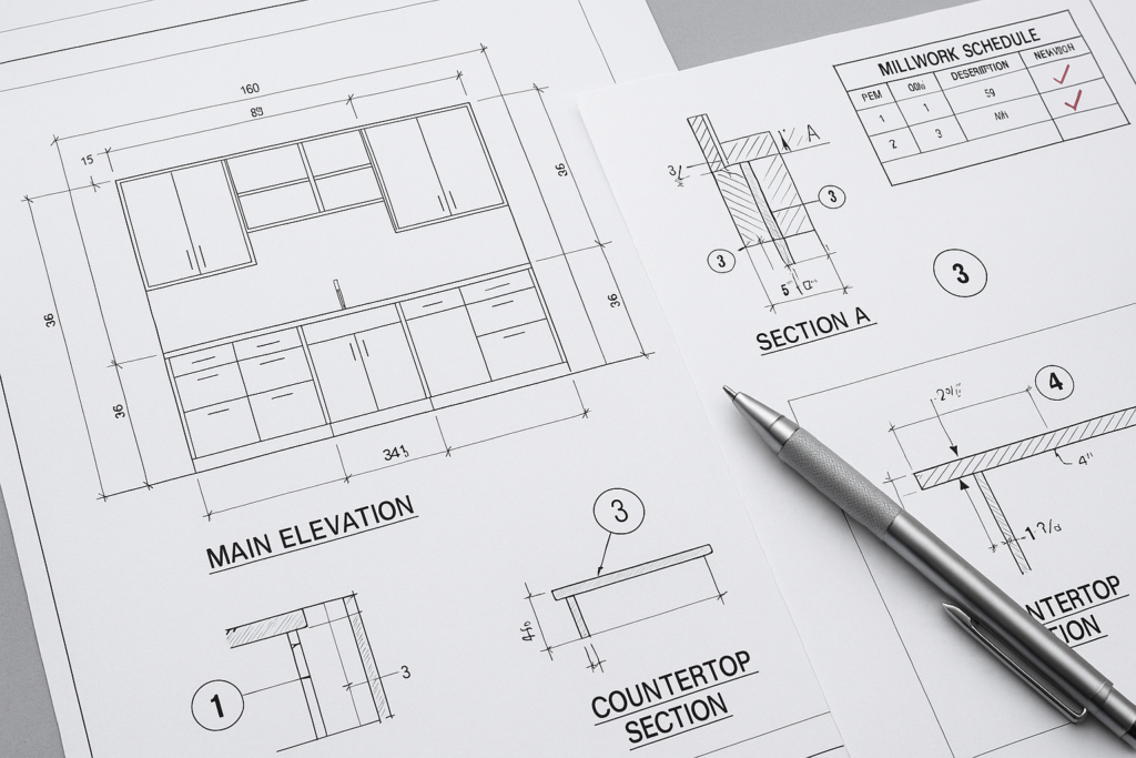
Fabrication drawings for architectural millwork show exactly how a piece will be built, sized, assembled, finished, and coordinated before it reaches the shop floor or jobsite. In the context of millwork shop drawings, they typically include dimensions, elevations, sections, material callouts, hardware, joinery, finish information, field-verification notes, and references to related conditions. For general contractors, architects, project managers, and millwork shops, the key point is simple: good fabrication drawings reduce ambiguity during approval, purchasing, production, and installation. Poorly coordinated drawings do the opposite, leading to RFIs, redlines, rework, and schedule pressure.
That is why fabrication-level detail matters so much inside architectural shop drawings and millwork submittals. The drawings are not just a formality for approval. They are the communication bridge between design intent and manufacturable reality. When that bridge is clear, teams move faster. When it is vague, every downstream phase slows down.
What fabrication drawings include in millwork shop drawings
If someone asks what fabrication drawings include, the practical answer is: everything needed to interpret, approve, build, and install the millwork correctly. The exact package varies by scope, but most strong millwork shop drawings contain the following core elements.
1. Plan, elevation, and section views
These views show overall size, visible design intent, and critical construction relationships. Elevations communicate the face appearance. Sections explain build-up, panel thicknesses, reveals, support conditions, and hidden details that cannot be understood from elevation alone.
2. Dimensions and tolerances
Dimensions should identify overall sizes, component sizes, clearances, filler conditions, toe kicks, countertop overhangs, and any relationship to field conditions. In many submittals, approval delays happen because dimensions are incomplete, duplicated inconsistently, or not tied back to site verification notes.
3. Material specifications
Fabrication drawings should clearly identify substrate, veneer species, laminate, solid stock, edge treatment, backing, core type, and any required fire-rated or moisture-resistant material conditions. If the material schedule is vague, the shop, GC, and architect may all interpret the scope differently.
4. Hardware and accessory information
Drawer slides, hinges, shelf pins, locks, pulls, support brackets, grommets, and specialty hardware should be shown or scheduled in a way that supports purchasing and fabrication. Hardware omissions are one of the most common sources of late-stage revisions.
5. Joinery and construction notes
Not every architectural submittal needs deep manufacturing detail, but fabrication-ready millwork drafting should explain enough about assembly to prevent confusion. That can include dadoes, confirmat fasteners, dowels, applied panels, removable backs, cleats, scribes, and fastening methods where they affect performance or appearance.
6. Finish references
Finish notes should align with the project finish schedule and clarify what gets finished, what is concealed, and what needs field touch-up or protection. A drawing package may also note grain direction, sheen, stain match, laminate code, or paint system where relevant.
7. Coordination with adjacent trades
Architectural millwork often interfaces with electrical, plumbing, stone, glazing, framing, and finish trades. Fabrication drawings should identify these touchpoints early. Power access in reception desks, sink cutouts in casework, blocking for wall panels, and appliance openings in break rooms are all examples where coordination belongs on the drawings, not only in emails.
8. Field verification and exclusions
Strong millwork submittals identify dimensions to be field verified, conditions by others, and assumptions used for drafting. This protects the project team from approving drawings that look complete but depend on unconfirmed site conditions.
How fabrication drawings affect architectural shop drawings
Fabrication drawings are not separate from architectural shop drawings; they often represent the deeper level of detail that turns design intent into buildable information. A concept detail from the architect may establish appearance and performance, but the millwork shop drawing package is where dimensions, material transitions, and practical construction logic are resolved.
For GCs and architects, this means approval should not focus only on whether the front elevation “looks right.” It should also consider whether the drawing package is coordinated enough to support procurement and fabrication without creating hidden conflicts.
Design intent versus fabrication intent
Architectural drawings define what the project should be. Fabrication drawings define how the millwork will be produced to achieve that result. The two should align, but they are not identical.
For example, an architect may draw a clean wood feature wall with evenly spaced reveals. The fabrication-level drawing must then resolve:
- Panel sizes based on material sheet yield and handling
- Attachment method to substrate or framing
- Reveal backing and alignment at inside corners
- Access panel integration if devices are hidden behind the wall
- Sequencing for install around flooring, ceiling, or glazing
Without that second layer of resolution, the millwork can be approved visually but still fail during production or installation.
Why detail level matters by project phase
At bid stage, a simplified package may be enough to communicate scope. At submittal stage, however, the detail level should support approval and production planning. At release-for-fabrication stage, unresolved dimensions, hardware questions, and finish assumptions should be minimized or clearly tracked.
This is where disciplined millwork drafting becomes valuable. It helps teams move from broad design information to a usable, reviewable, buildable package.
What GCs, architects, and millwork shops should check before approval
The fastest way to improve drawing quality is to review it with role-specific priorities. Each stakeholder tends to see different risks.
GC checklist
- Do the drawings match the latest architectural backgrounds and reflected ceiling plans where relevant?
- Are field dimensions identified clearly, especially for walls, soffits, and existing conditions?
- Are trade coordination points noted for power, plumbing, blocking, countertop templates, or devices?
- Are lead-time items such as specialty hardware or finish materials identified?
- Do the submittals define scope boundaries and items by others?
- Are installation clearances and access needs realistic for the site sequence?
Architect checklist
- Does the visible design align with the intended elevations, proportions, and reveal logic?
- Do material and finish callouts match the project specifications and finish schedule?
- Are edge conditions, grain direction, and exposed surfaces handled correctly?
- Do details preserve the design intent at corners, terminations, and transitions?
- Are substitutions or practical modifications clearly disclosed instead of hidden?
- Are accessibility, code-related, or performance-related dimensions maintained?
Millwork shop checklist
- Can the assembly actually be fabricated with the specified materials and hardware?
- Are there dimension conflicts between plan, elevation, section, and schedule?
- Are any details underdefined for purchasing or CNC/programming prep?
- Are support methods and wall conditions known?
- Have finish sequences and protection requirements been considered?
- Are revision clouds, redlines, and approval comments fully incorporated?
Practical examples of what to catch early
Example 1: Reception desk with power and transaction top
A reception desk may look complete in elevation, but fabrication drawings should also show wire management, access panels, support for the transaction counter, finished versus unfinished interior surfaces, and seam locations if the top exceeds sheet or stone handling limits. If these items are missing, the GC may approve the drawing only to discover installation conflicts later.
Example 2: Break room base cabinets under countertop by others
In this case, the millwork shop drawings should identify appliance openings, required fillers, countertop template dependencies, plumbing rough-in zones, and wall irregularity allowances. A clean-looking cabinet run can still fail in the field if no one accounted for outlet placement or a shifted sink centerline.
Example 3: Veneered wall panels at elevator lobby
Architectural shop drawings for panel systems should resolve panel module size, reveal alignment across corners, backing, attachment, substrate conditions, and access requirements for devices or concealed doors. A visual mismatch in grain or reveal spacing is often the result of incomplete fabrication thinking, not poor installation alone.
Common mistakes and approval delays to avoid
Many review cycles get longer for the same predictable reasons. Knowing these issues helps teams prevent them before submittal.
Incomplete dimensions
Missing overall heights, inconsistent widths, and unresolved filler dimensions force reviewers to make assumptions. That slows approval and creates risk.
Uncoordinated hardware
Hardware shown generically in one place and specifically in another leads to confusion in pricing and production. Every cabinet type should be easy to interpret without cross-checking multiple conflicting notes.
Ignoring field conditions
Walls are rarely perfect. Existing conditions are rarely exact. If a drawing package does not identify field verification requirements, someone will likely fabricate too early or install with avoidable gaps.
Revision control problems
One of the biggest causes of wasted time is a submittal set that includes old notes, unreconciled redlines, or revised sheets that do not match schedules. Clean revision management matters as much as drafting quality.
Overly generic notes
Notes like “verify in field” or “contractor to coordinate” are useful only when tied to specific conditions. Broad, repetitive disclaimers do not replace actual coordination.
Not showing enough sections
Reviewers often approve a nice elevation without understanding the construction behind it. Strategic sections and detail blowups can prevent large misunderstandings with very little added drafting effort.
How MillworkIQ helps teams produce clearer millwork shop drawings
When schedules are tight, the practical challenge is not just creating drawings. It is creating drawing packages that are clear enough for review, coordinated enough for submittal, and organized enough for fabrication release. That is where MillworkIQ fits naturally into the workflow.
MillworkIQ supports shops, contractors, and design teams with drafting, redline incorporation, submittal cleanup, dimension coordination, and revision-ready drawing organization. Instead of pushing around incomplete sheets internally and losing time between comments, teams can use a focused drafting partner to turn partial markups into cleaner, more reviewable millwork shop drawings.
If your team needs help with ongoing drafting capacity, detailed review support, or better submittal organization, MillworkIQ’s services are directly aligned with architectural millwork production needs.
When it makes sense to bring in support
- Your shop has design intent drawings but not enough internal drafting bandwidth
- Submittals are getting delayed by repeated redline cycles
- A project includes many similar casework or panelized conditions that need consistency
- You need cleaner dimensions, schedules, and coordination notes before architect review
- Approval comments must be incorporated quickly without creating sheet conflicts
What a stronger submittal package looks like
A stronger package is easier to approve because each sheet answers the reviewer’s likely questions before they are asked. It includes clear references, coordinated schedules, consistent dimensions, and enough detail to support fabrication logic. If you want to see the level of output expected for presentation and production support, review the MillworkIQ portfolio.
Simple decision guide for teams reviewing fabrication drawings
Before approving or returning a submittal, ask these three questions:
- Is the design intent preserved? Check visual appearance, materials, finish, proportions, and required performance.
- Is the fabrication intent clear? Check dimensions, sections, hardware, support, and build logic.
- Is the project coordination explicit? Check field verification, trade interfaces, exclusions, and sequencing notes.
If the answer to any of these is no, the drawings may still be useful, but they are not yet fully reliable for approval and release.
FAQ
What is the difference between millwork shop drawings and fabrication drawings?
Millwork shop drawings are the formal submittal drawings used to communicate and approve the millwork scope. Fabrication drawings are the more detailed build-focused information within or following that package that supports production. In practice, many teams use the terms interchangeably when the shop drawing set is detailed enough for fabrication.
What should be included in millwork submittals?
Most millwork submittals should include plans, elevations, sections, key dimensions, material and finish callouts, hardware information, relevant details, and coordination notes for field conditions or trade interfaces.
Why do architectural shop drawings get rejected or delayed?
Common reasons include incomplete dimensions, vague notes, inconsistent schedules, missing sections, hardware conflicts, and unresolved field conditions. Delays also happen when redline revisions are incorporated inconsistently across sheets.
Who is responsible for checking fabrication drawings?
Responsibility is shared. The millwork shop checks buildability and completeness, the GC checks coordination and scope alignment, and the architect checks design intent, specification alignment, and visible finish outcomes.
Final takeaway
The best fabrication drawings do more than describe a cabinet or panel. They remove uncertainty from approval, purchasing, production, and installation. For GCs and architects, that means reviewing millwork shop drawings for both design accuracy and fabrication clarity. For millwork shops, it means creating submittals that answer real project questions before they become costly delays.
If your team needs help drafting new sheets, cleaning up redlines, or organizing a stronger submittal package, request a MillworkIQ quote for shop drawing drafting, revision support, or submittal coordination.